This part explains the software update procedures for MB33 and MB36 model clients. There are 2 different types of updating;
- Analog Software Update : In this part connections, update details, software update, and usb update are explained.
- IP Software Update : Console update and ethernet update are described in this section.
Analog Software Update
Before starting software update operation it is mandatory to get correct configuration parameters of client. Each version of firmware for analog card must be released according to panel type and panel size of client because of the timings of LCD panel. So you should first enter into “Service Settings” menu by pressing “Menu + 4725” on remote keyboard and select “Product Info” from the menu.
The data written is “Pcf” variable defines the firmware type of analog card. You should request correct firmware according to this variable.
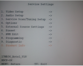
Figure 1: Service Settings Menu
Update procedure must be with extreme caution, only correct firmware which will be specially designed to work with client (for given PCF data) must be written to analog card. The LVDS timings are different for different panel sizes and panel types.
Note : Writing different firmware may cause unwanted effects and may brick your client !!!
This part of document describes the usage of third party software which does not belong to VESTEL. Every step must be performed with high caution. VESTEL, ZORLU shall have no liability for the accuracy or correctness of the content of this document and any damages caused in any way to your computer systems or target TVs.
Connections
The programming tool contains 3 parts, DB07 card, USB cable for connecting programmer card to PC and special SCART cable for connecting programmer card to client. Connect USB cable to PC and SCART cable to SCART1 interface of client.
Update Details
Figure 2 displays programmer software interface. We will first press “Connect” button for establishing connection between PC and client. If you receive “Can’t find device type” message, you should control connections and cables. (Also restarting client may help). You’ll receive a popup window displaying device type upon successful connection.
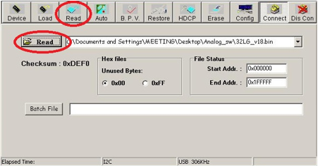
Figure 2: Programming Tool
First step is to read the firmware image so we will press “Read” button on top menu and select the necessary firmware as shown in Figure 2. Next step we will choose basic configuration parameters for analog software update procedure so we press “Auto” button and open configuration menu. Then we will unselect following items in menu;
- Re-Connect
- Blank
- Verify
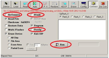
Figure 3: Update Operation
Now we are ready to perform update operation, we will press “Run” button and the update operation will start. During update operation you’ll see current progress on the bar and after seeing “Pass” message on window, press “Disconnect” button and restart the client.
Software Update
There are two different client releases for clients hardware and all of them named as “version_X.YY.Z.zip”, major release numbers represented by X and minor release numbers represented by Y.
USB Update
This section explains how to perform update operation by using USB which is very easy to perform and highly recommended to recover problematic situations. Basically system has two stages, writing “USB update images” to and USB stick (min. 512MB) and rebooting clients with using this USB stick. The USB update image is designed specifically to perform update operation and contains actual release images in side.
Note : The USB update image is in EXT3 format, so we should not format USB disk by windows formats such as FAT32, NTFS, etc.
There are two different ways to prepare USB update image based on your operating system; using windows tools or using Linux. You are free to choose one of them.
Writing Images Using Linux
Naturally preparing an USB is easy in Linux by using its own console tools. You can follow listed steps bellow;
- Extract “version_X.YY.Z.zip” file and get “version_X.YY.Z.ext3” file.
- Plug USB stick to your host PC and learn its mount point (as an example /dev/sdb1)
- Write image to USB by using a simple “cat” command shown below
root@bora-laptop:/USBUPGRADE# cat version_1.10.0.ext3 > /dev/sdb1 |
Writing Images Using Windows
In order to prepare “Update USB” under Windows we need to use “ImageWriter” application. You can download this application from our FTP servers and perform following steps to prepare update USB.
- Download the latest version of ImageWriter and run ImageWriter.exe
- Select “version_X.YY.Z.zip” or “version_X.YY.Z.ext3” file.
- Select USB Device drive
- Start writing update image to USB stick
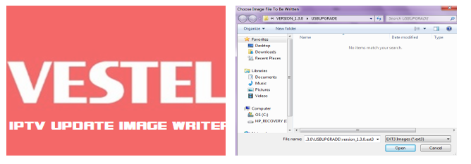
Figure 5: Image Writer for Windows
Compatible Operating Systems:ImageWriter executable is compatible with the following operation systems
- Windows Server 2003 & Windows Server 2008
- Windows XP SP1, SP2, SP3
- Windows 7
Updating TVs/STBs
Update operation is simple task that consist of two steps, plugging update USB into client and restarting it. During update operation, an image will be displayed on client screen which will show the progress and the notification image at the end of update. (Figure 6) Basically you can follow following stages;
- Plugging Update USB
- Update Operation
- Removing USB Disk and restarting clients

Figure 6: Update Images
Ethernet Update
Log in to “HotelTV Admin Tool” and choose “Administration” menu, you will see the list of TVs which are free to invoke several operations. Choose the client(s) that you want to update and press next button, then you’ll get the flowing screen (Figure 7). This page allows you to operate different instructions on client(s).
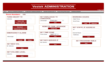
Figure 7: Client Management Screen on Administration Menu
Console Update
We expect USB update or Ethernet update will work without any error but sometimes there may be situations that these updates may fail. This section describes how to perform software update over console using serial cables. HotelTV1 works with MB33 and MB36 series clients and each model has different hardware connection for serial cabling. We can understand client model by looking the location of the Ethernet port; on MB33 model clients Ethernet port is located on side and on MB36 model clients Ethernet port located on back of client.

Figure 8: Secret Service Menu
By default console output will be closed for debugging, we will have no output even if we connect serial cable to TV. So we have to enter service menu and open console output for debugging. As seen in Figure 8 you should first enter in service menu and select “8. Programming” then under this menu you should select “6. DTV Download” and set “On”.
Now client is ready to debug over serial cable, we will open a terminal program on PC and connect with following settings. (You can use your favorite program, Kermit, Putty, Teraterm, etc …)
115200 baudrate No parity No hw control No flow control |
When we establish connection to client then we will get lots of debug logs, the key is to catch boot sequence in bootloader stage in order to write different banks of flash memory trough bootloader console. So we will keep terminal program open and restart the client, quickly press menu+4725, then 8-6 and set open. And press any key on terminal program in PC. This combination will bring us in following bootloader console:
Vestel> |
Next thing is to give “loadb” command on bootloader console and send the kernel image through your favorite terminal program using Kermit protocol. At the end on console it will display the location of kernel image in memory banks. We will use this address while copying kernel image from ram to flash.
The source address of “cp.b” command which is highlighted with red color in below indicates the start address of the kernel image in memory which we transmitted trough terminal program using Kermit protocol.
> loadb ## Send the image file “vmlinux.ub” file for kernel via terminal program Vestel> protect off 1:10-60 Vestel> erase 1:10-60 Vestel> cp.b 0x84000000 0xa0040000 $filesize Vestel> protect on 1:10-60 |

