In the following sections; Video Wall Configuration will be explained with images and details. Port solutions, accessory box contents, Input/Output ports, RS232 and IR daisy chain connection, controlling with an external PC, IR Daisy-Chain connection, VW user menu specifications are explaning in this document.
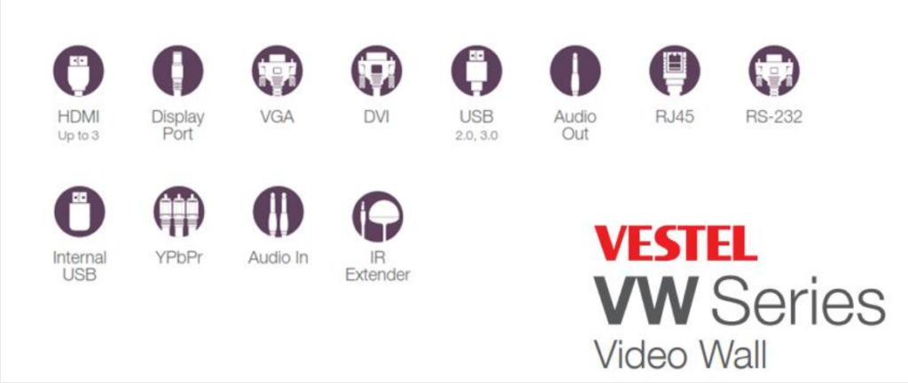
Port Solutions: This section explains port solutions like HDMI, VGA, USB etc.
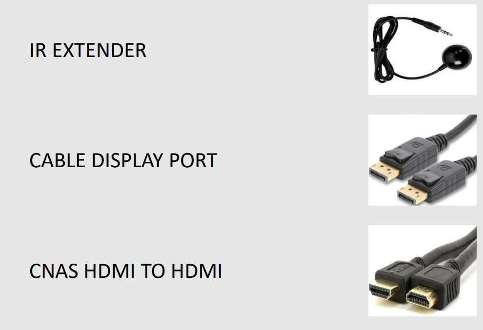
Accessory Box Contents: This section shows accessory box contents which are IR extender, HDMI cable.
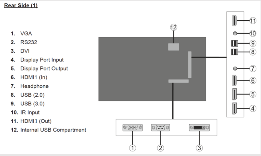
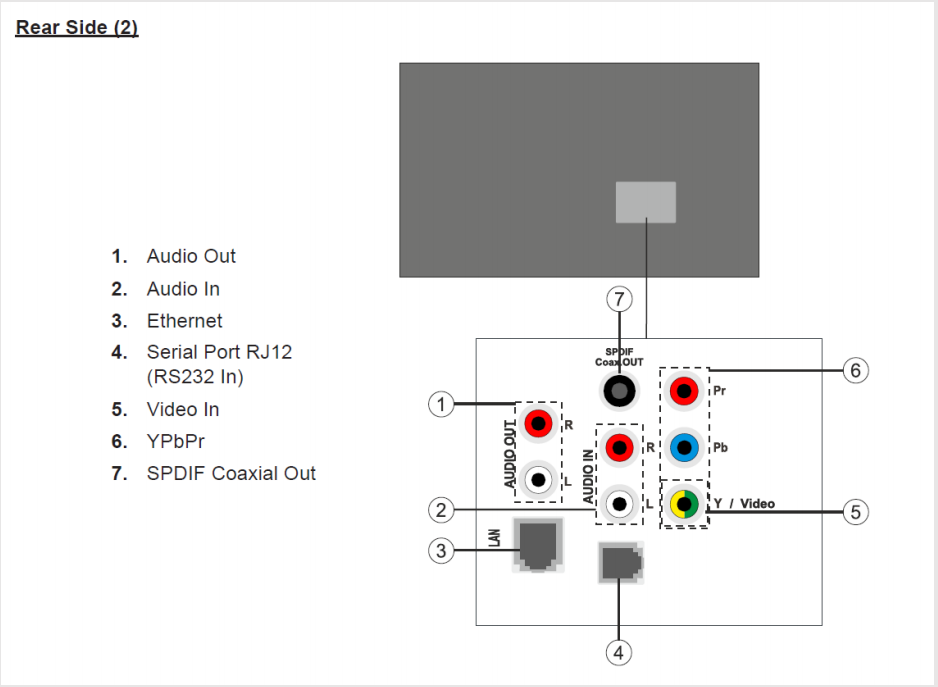
Input/Output Ports: Input/Output ports on the screen and their images are shown in this section.
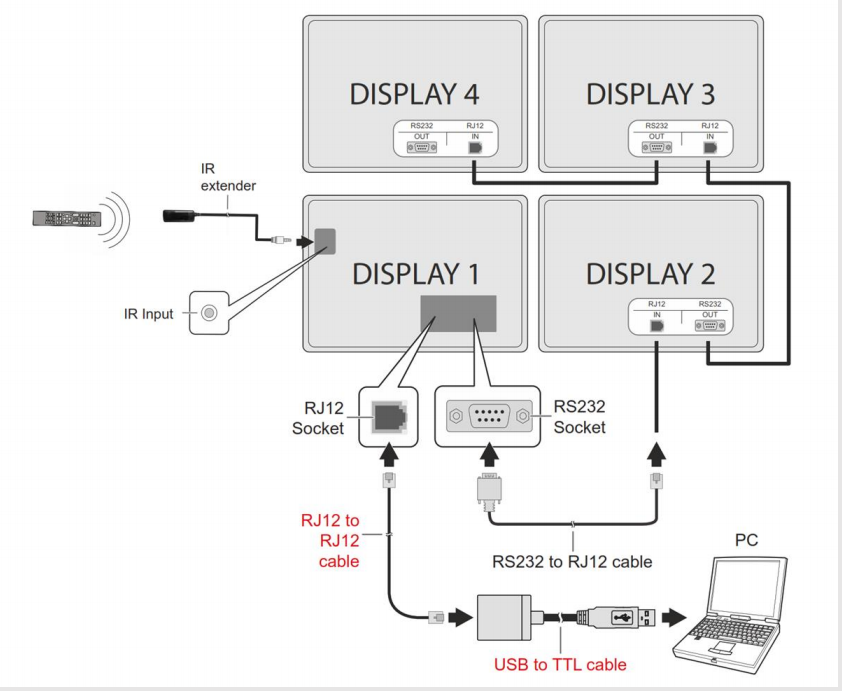
RS232 and IR Daisy Chain Connection: This section explains RS232 connection information.
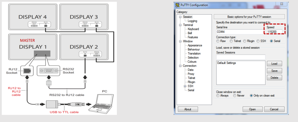
Controlling with an External PC: Connecting from an external PC via RS-232 (COM port) or LAN (Ethernet port) on the PC is explaining in this section.
IR Daisy-Chain Connection: This section includes Connected units, device ID, master settings etc.
VW User Menu: This section explains User menu and Video Wall settings
Specifications: In this section there is an example of this system.
Figure-5: Connection Schema
Controlling with an External PC
This section will explain controlling with an external PC. You can control the product from an external PC via RS-232 (COM port) or LAN (Ethernet port) on the PC. For instance, system source can be changed by RS-232 from remote computer. When a command is sent from the PC to the product, the product operates according to the received command and sends a response message to the PC. Figure-6 shows this information.
Note: Note that if the command is entered without the signage id, the command will be sent to all connected Displays.
Figure-6: External PC control schema
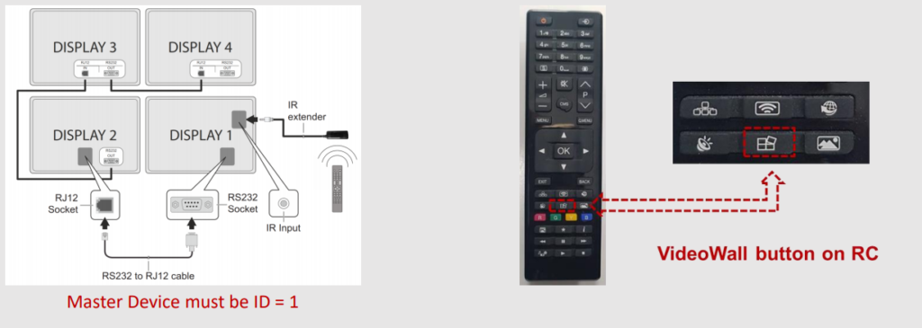
IR Daisy-Chain Connection
You can use this type of connection to relay the remote-control signals to the connected units. The signage ID of the display, to which the IR extender is connected (so-called wall master), should be set as “1” first using the Signage Settings > Set ID menu.
A number will be displayed on the screen when the Video Wall button on the remote is pressed next time indicating the Signage ID of the device which can be controlled via the remote. In order to control a specific display in a video wall matrix its signage ID should be entered using the numeric buttons on the remote after pressing the Video Wall button. To control all connected displays this value should be set as “0”. If set as “1” only the wall master can be controlled via the remote.
This information will be shown in Figure-7.
Figure-7: Video Wall Device Schema and remote controller button
VW User Menu
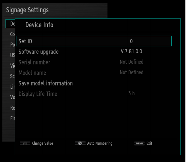
You can see Device Info with following steps below on remote control.
MENU➔ Signage Settings ➔ Device Info
- Set ID: Product ID in the system. It is used in RS232 communication and communication with the product is performed by using this ID if any product in the system is to be commanded.
- Software Upgrade : Shows software information on the product. Save Model Information: Save to USB this all information for CS.
- Display Life Time: It shows the working time of the panel after the product is produced.
- Serial Number: The serial number of the product which is written in production line.
- Model Name: Model name of the product which is written in production line.
You can see this informations in Figure-8.
Figure-8: Device Info
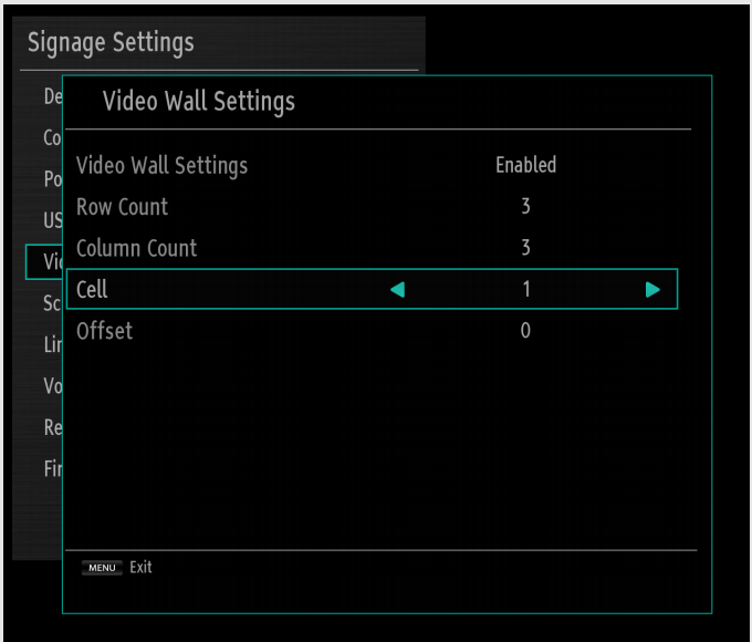
You can see Video Wall Settings with following steps below on remote control.
MENU➔Signage settings➔Video Wall Settings
The number of rows and columns are entered according to the system installed.
The video is divided into the units by this configuration.
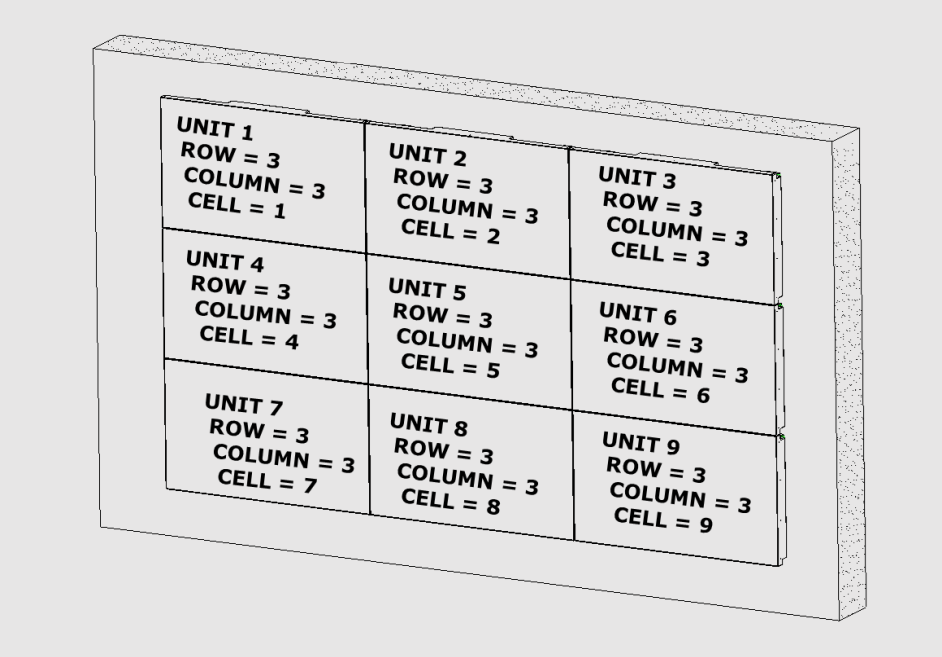
For a 2×3 VideoWall, the number of rows should be 2, the number of columns should be 3. The numbers of “Cell” are as follows. If the set TV is 1 TV, “Cell” should be set to “1”. For a full screen image, the cell number should be “0”.
You can see this informations in Figure-9 and Figure-10.
Figure-9: Video Wall Settings
Figure-10: Video Wall Unit Schema
Specifications
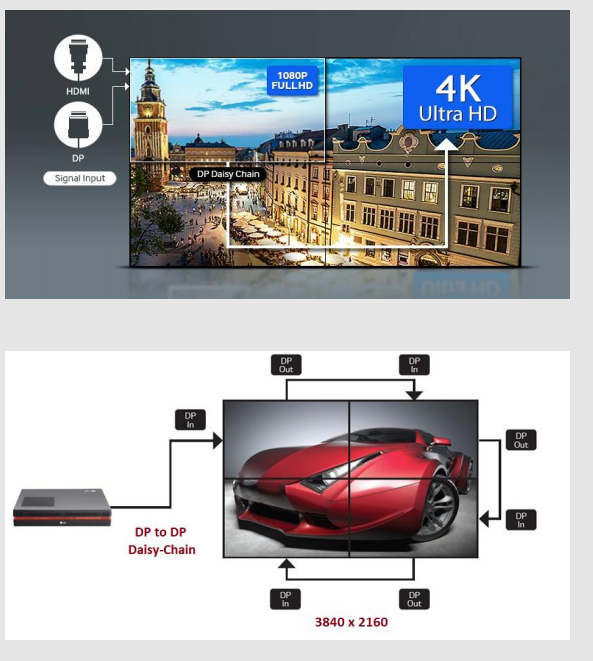
Mirror content across multiple displays, using a single connection between every two devices. Offering both DisplayPort or HDMI input and output, these daisy-chainable monitors can be set up as a video wall.
Note: Which port to start with that port should be continued.
There is an example in Figure-11.


