Vsync is an application that provides video synchronization over the network with multiple client displays. In the following sections; Vsync video synchronization application will be described with further details under the headlines below:
- Synchronization: Main entry point as a button for Vsync synchronous video player application.
- Vsync Admin Application: Vsync’s video setting adjustments application for the system administrator user.
- Informal Layout: Main page for designing asymmetrical design layouts for displays with minimum 1920×1080 resolution.
Synchronization
Synchronization button redirects to “Vsync”. Vsync plays video through its own player. Vsync’s purpose is to play synchronous video on regular and uneven (asymmetrical) video wall installations, where the VS plays its own video.
Setup
| Requirements | |
| Operating System | Windows Server 2012 |
| Working Environment | .NET 4.5.2 |
| Database | MsSQL Server |
| Server | IIS* |
| VS Platform | MB120DS** |
Table 1: System Requirements
URL Rewrite module should be added to IIS. For this operation, firstly IIS is opened. Then, Web Platform Installer is opened. In the pop-up window, search operation is handled by “url write” and the module will be loaded. Additionally, VS software should be up to date.
Figure 1: Management
Setup Process
Setup file is opened. In the pop-up window, “I accept the terms in the License Agreement” is selected and “Install” button is clicked. When the setup operation is successful, “Completed the Vsync Setup Wizard” text will be appeared.
After installation, management interface is attained by http://SERVER-IP/vsync/admin. VSs added to the system should connect to the http://SERVER-IP/vsync address. User and password information for the connection is shown below.
| Access | |
| User Name | admin |
| Password | vestek |
Table 2: Rotation Setup Outline
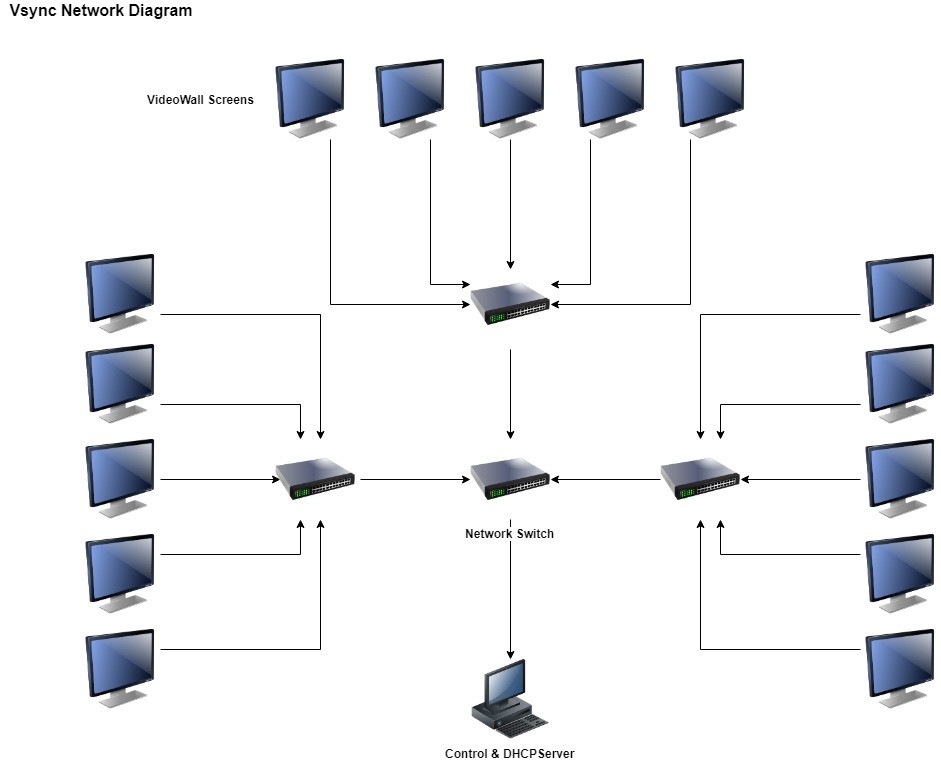
VSync Network Diagram
Figure 2: Vsync Network Diagram
VSync Admin Application
In Vsync, VS and video adjustments are managed by Vsync Admin application which contains 6 basic components: Groups, File Management, Command Sender, Controller, User Management, Settings.
Video Specifications
Synchronization application runs with .h264/.h265 codecs that have mp4 container. It’s videos should be coded with a proper tool. The coding parameters should not be higher than the parameters indicated in MB120 specs. The videos should have ratio 16:9 and resolutions 720p, 1080p, 1440p and 2160p. Moreover, the conditions below increase synchronication performance:
- Not having audio in the video.
- Scattering video l-farames properly.
- Having constant framerate.
- High framerate. (Preferably 60 or 50 frame/sec)
- Having low Bitrate. (Preferably around 10Mbps)
Admin Main Page
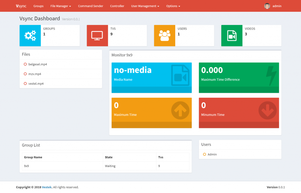
Admin main page is a general page shows files, statistics, VS conditions and users. Monitor part shows group information. The groups are changing based on periods. Information in the main page is:
- Media Name: Name of the video running by the group.
- Maximum Time: The time in the video as the time in the VS is the most advanced information.
- Minimum Time: The time of the video in the VS is the most recent information.
- Maximum Time Difference: The difference between maximum and minumum time.
- Duration: The length of the video being played.
The figure below displays Vsync dashboard. This board contains groups, VSs, users and the videos.
Figure 3: Dashboard
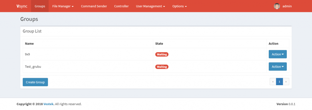
Groups
With this component, VSs can be divided into various groups and different synchronization scenarios can be implemented. The current state of the group will also be visible on the table.
Figure 4: List of Groups
Adding Groups
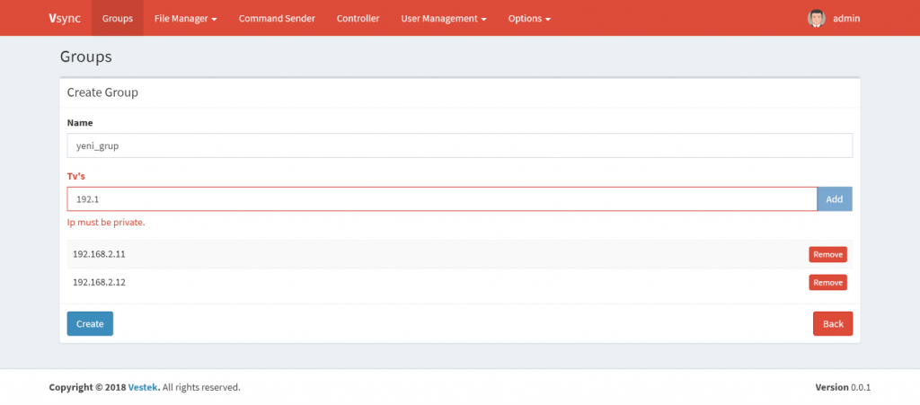
In the Groups, button “Create Group” is selected and group adding page is opened. The figure below indicates this group creation.
Figure 5: Creating Groups
When adding the groups, the group names and VSs private IPs are entered respectively. After finishing this process; “Create” button is selected and a group can be created.
Group Management
In the Groups, for any group, by using “Action” button, below actions can be handled:
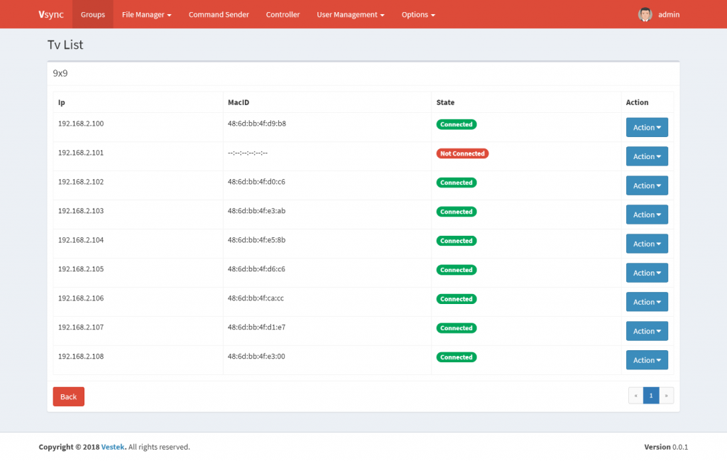
- Manage: By pressing this button, group management screen is opened. VSs’ conditions can be displayed.
Figure 6: Group VS List
With “Action” button, these operations can be handled:
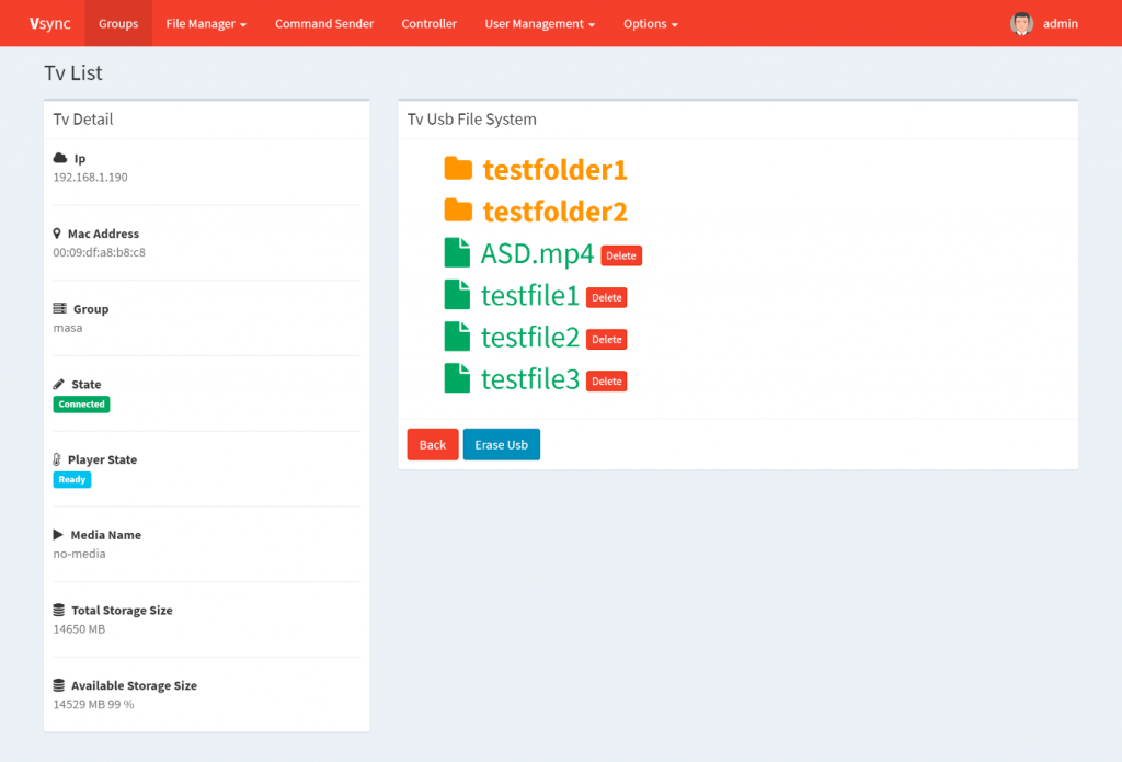
- Details: On this screen, details of VS conditions and contents of attached USB can be shown. USB can be formatted or files inside can be deleted.
Figure 7: VS Details
- Delete: Selected VS is deleted from the group.
- Identity On – Off: With this button on the VS interface, information about VS IP, MAC ID can be displayed (This specification can not work due to plugin. When the plugin is corrected, it will work.)
- Image On – Off:On the VS interface, images can be displayed (In USB’s root directory “image.jpg” named images).
- Delete: With this button the groups can be deleted.
File Management
Under file managent subject; file related operations such as download and upload management, are described with further detail below.
Download Management
For download management, file transfer to the groups or VSs can be handled. Files that are scheduled to download to VSs should be sent to the server using the installation method.
Figure 8: Download Management
Download Type
Single File: It downloads any file to the target.
Seperate File: It downloads a special file to the VS. In the Files tab, compatible files are listed. Format should be “FileName_GroupName_VSIP.mp4” for the seperate files.
Target (Sent-To) Type
Group: It sends files to the whole group.
TV: Only sends files to a single VS.
Note: When Seperate Files and Group are selected together, all VSs in the groups should have same file name structure. For example:
“Video_Group1_192.168.0.10.mp4”
“Video_Group1_192.168.0.11.mp4”
“Video_Group1_192.168.0.12.mp4”
After above selections are made, file, group, VS to be downloaded are chosen and “Start” button is selected.
Upload Management
In this page, files can be sent to the server. After that process, these files can be loaded to the VSs using dowloading process. Files to be uploaded should contain English letters, numbers and standard characters. The figure below shows uploading a file to the server.
Figure 9: File Upload
Command Sender
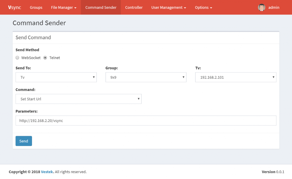
This component can send to the VSs LAN commands individually/collectively, or with Telnet/WebSocket protocols. For sending WebSocket commands, VSs should be attached to the system. After sending the parameters below (Image 9), “Send” button is pressed.
Figure 10: Sending Commands to The VS
- Send To: The destination to, which the command is sent, is selected.
- All: Commands are sent to the all VSs on the system.
- Group: Commands are sent to the selected groups.
- TV: Commands are sent to the selected VSs.
- Group: Occurs when group or VS is selected as the destination target.
- TV: Occurs when VS is selected as the destination target.
- Command: Commands to be sent to the VS are chosen and sent from here. For commands that are not in the list, “Other” option can be chosen.
- Parameter: The format that should be entered when the command is selected and shown here. When “Other” is selected, command to be sent should be entered completely.
Commands
- Set Start URL: When VS opens, it sets browser’s start page. An url is entered to the parameter part.
- Open URL: It opens the URL in the browser. This URL is written to the parameter part.
- Set Video Wall: It is used for video wall adjustments. RowCount-ColumnCount-Cell-Offset is written in the parameter part. As an example: for 4×4 video wall from upper left corner and for second VS 4-4-2-0 is written.
- Restart: It is used for VS restart operation.
- Start USB SW Update: It uses USB (plugged into the VS) software and updates VS software.
- Start USB Operations: It is executed for the implementation of files such as panel and profile for VS.
- Set User Security Level: For some telnet commands, user should be set security level Admin. In the parameter part, ADMIN/USER XXXX should be written. XXXX is a PIN value set after FTI. For example: ADMIN 0000 or USER 0000.
- Others: It is used for sending command are not found above. Commands are set similar to telnet interface.
Controller
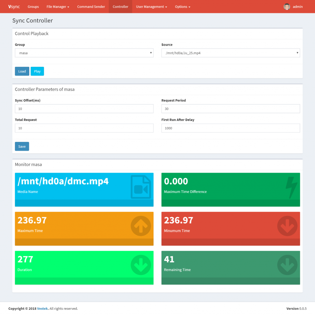
Contents to be played are selected and parameters are entered related to synchronization. Moreover, the synchronization’s status can be seen in the monitor part.
Playback Control
In this section, video’s playback status can be controlled. Video can be uploaded and played. Load button is used for video reloading to be played by the VS. For playing loaded video, “Play” button is pressed. Black screen can appear after play button. However after VS synchronization, the black screen will dissappear. This can be observed from the Monitor.
Parameters
Parameters related to the synchronization are entered and “Save” button is pressed. Below are some explanations about these parameters.
- Sync Offset(ms): It shows synchronization sensitivity. Reducing or increasing too much can cause no sync. Optimum values according to Framerate:
- 60 fps: 18ms
- 50 fps: 21ms
- 30 fps: 25ms
- 25 fps : 30ms
- Other values: These parts are used for testing synchronization algorithm. It will be removed in the finale version.
Monitor
Instant synchronization status of the selected group can be displayed in the playback control.
- Media Name: Name of the video played by the group.
- Maximum Time: The time in the video as the time in the VS is the most advanced information.
- Minimum Time: The time of the video in the VS is the most recent information.
- Maximum Time Difference: The difference between minumum and maximum time.
- Duration: The length of the video.
- Remaining Time: Remaining time of the video.
Figure 11: Playback Controller Page
User Management
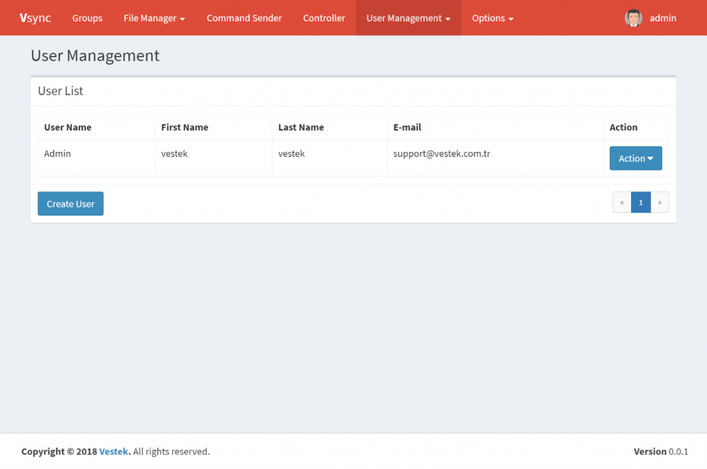
Under User Management tab, user management operations such as listing, adding, editing and deleting is described with further detail. Additionally, users roles can be added and permissions can be given to these roles and users.
Listing Users
User Management -> Users page is opened. This page can be seen in the figure below.
Figure 12: User Management
Adding Users
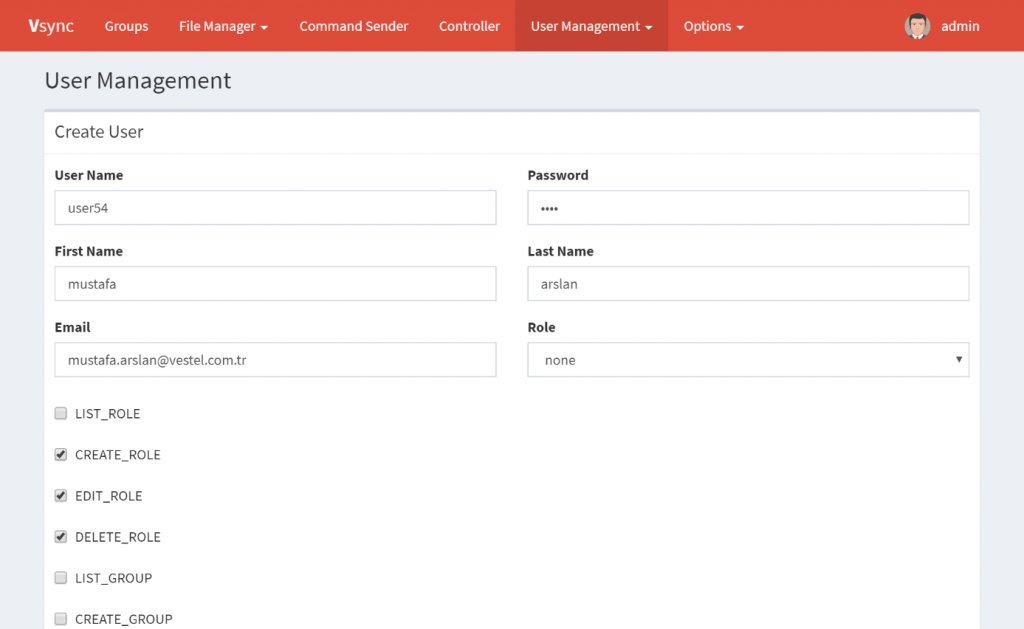
“Create User” button is pressed after listing users. The requested information is entered and “Create” button is clicked. By doing this, the users are created.
If the user has been assigned a role and the permission has been added on this page, the user will have a combination of two permission sets. The figure below displays the users adding process.
Figure 13: Adding Users
Editing Users
After users are listed, for users to be edited, “Action” button can be used. In the pop-up window “Edit” button is pressed. The user is edited and “Save” button can be used.
Deleting Users
After users are listed, for users to be deleted, “Action” button can be used. In the pop-up window, “Delete” button is pressed. The confirmation window is confirmed and the user is deleted.
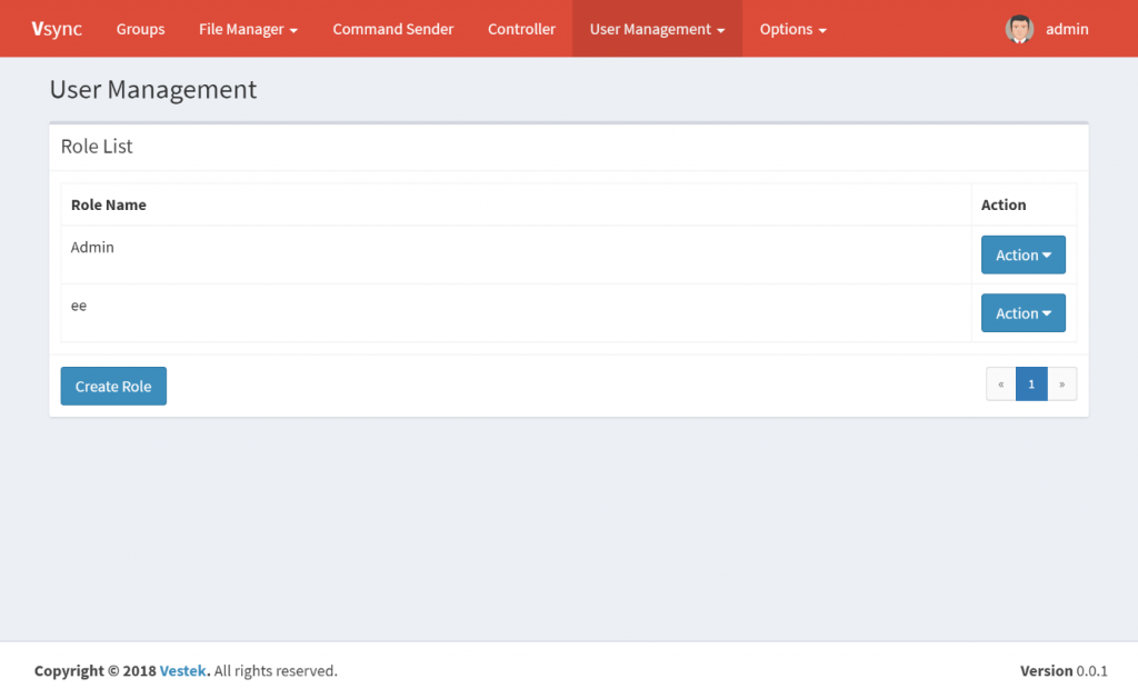
Listing Roles
User Management -> Roles page is opened. An example page is displayed in the figure below.
Figure 14: Role Management
Roles
Users may have the following roles.
- Super Admin: This role can access everything. Only one can be found in the system. At the end of the installation this user is created with the “admin” user name.
- Admin: This role can access everything except user management.
- Moderator: This role can access Dashboard, Groups and Controller; but it can’t edit Groups.
Options
Under options tab, the user can set and edit related application notification settings. The user sets relevant notifications with the required SMTP settings, in order to report error and important events (Figure 15). When Active option is selected, it will notify the e-mail address entered by “Send-To” from the SMTP server with the related settings.
Figure 15: SMTP Configuration
Informal Layout
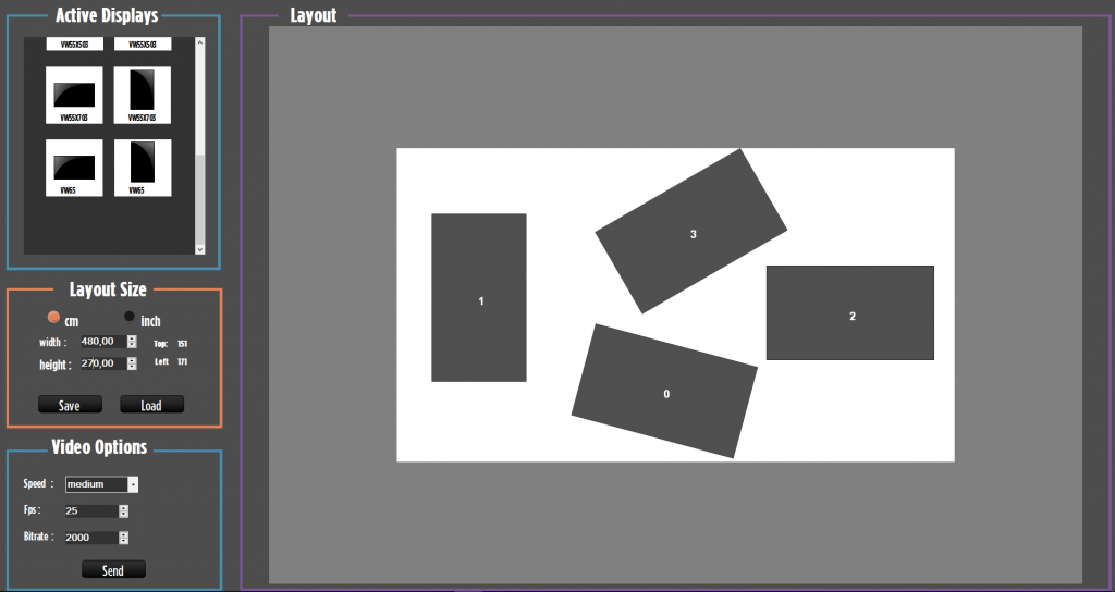
This part can be used with monitor with has minimum 1920×1080 resolution. The users can draw informal layout with displays.
To enter the Informal Layout page, move the cursor to the “Informal Layout” in Main Menu Items. And then click it and see the new opening pop up. If you do not have 1080p monitor, click the “Cancel” button. However, if you have 1080p monitor click “Ok” button and Please see figure below.
- Enter the ınformal layout width and height.
- Drag and drop the displays selected from Active Displays, inside the layout area.
- Displays can be moved, deleted, aligned and rotated.
- After creation of informal layout, click the “Send” button and see file explorer.
- Select the video from file explorer.
- Then, see the output video file named as out + DisplayID.
- Created Layout can be saved by clicking save button. Layouts are saved in “Saved Layout” folder under the application folder. It’s named automatically.
- Saved layout can be loaded by clicking load button.
Figure 16: Informal Layout Outline


